
How to serve customers
Basic principle: keep equal partnership with customers; provide economical and reasonable dU/dt filter and sine wave filter for customers.
Bajog can use own proprietary technology to supply customers with economical and reasonable solution and varied filters that the current could reach as high as 3500amp, dU/dt filter and sine wave filter included, of course.
In order to satisfy individual request of the customers, the series of dU/dt and sine wave filter produced by Bajog, their current from 1 to 1500 amp, clock frequency from 2kHz to 16kHz, the length of lead is 600m.
Important instance need understanding:
- Different systems and performance need different pertinence filter solution.
- What is the help can Bajog offer?
According to the information provided by customers, Bajog produce a basic model filter; expand several different functions through its exterior joint to satisfy the specific requirement of customers.
Meanwhile, Bajog also offer present test, laboratory test and hot-line telephone technological service to customers.
The materials used for filter is processing optimization selection, totally meet the demands of dU/dt(10KV/Ás to 500V/Ás), produce perfect sine wave shape with a little harmonic and size obey to the require of minimum. In this way, it can save space, time and expense.
Customers only have to pay for the expense of prototype model and reference test man-haur.
So far, if prepared enough, Bajog can complete the test task within one day and find an appropriate solution.
There is no doubt that Bajog has considered all the disadvantage factors carefully in the process of optimization, such as damp shake, temperature performance refer to long lead , feedback to the middle loop, all these are attributed to the characteristics of high level customer service. The du/dt filter of Bajog is fit for all the occasion that needs high technology, such as university, military appliance and industry.
Following are two different optimization projects which are result from the cooperation with Brandenburg. These projects are finished within one day.
1. Single-phase filter (tested under different clock frequency and result evaluation)
1.1 Single-modulate( 5kHz)
1.1.2 Total harmonic heft
In order to work out total harmonic heft, we have done a Fu Liye analysis to the wave function. Following wave curve is recorded by oscillograph and deposited in the form of ASCII. After treated with Excel, these files can be read by Simplorer process and be managed continually.
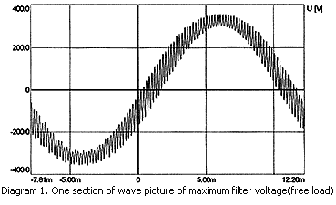
Middle line loop voltage is set at 400V; the recorded wave is obtained when the speed of oscillograph is at 10kbit/s.
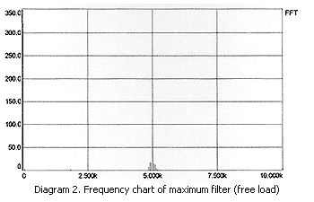
The value of 50kHz fundamental wave heft is UI=320.38V, the harmonic heft is very strong near 5kHz(pulse frequency), U5kHz=42.12V.
The calculation of harmonic distortion followed below:
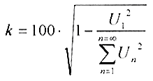
There is a certain requirement refer to wave shape, interrelated fundamental wave should cover 99.55% at least, harmonic distortion should less than 5%. We can append capacitors to cut down harmonic heft, 2 µF per capacitor.
The voltage wave shape record when six capacitors are appended under the circumstances of free load and rating induction load(22 kW, I = 13.5 A)
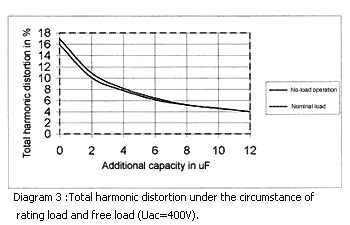
When 10 µF capacitance is added , harmonic distortion is 4.5%, and harmonic quantity also can be cut down by reducing the voltage of middle line.
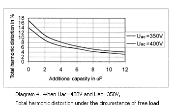
The voltage of middle line is 350V; this is to gain the least voltage that the 230V voltage output required. Harmonic heft is less 2% than the voltage is 400V. The additional protective capacitor only needs 8 µF, but 10 µF when the voltage is 400V. Therefore, in order to reduce the harmonic heft, thereby to reduce filter at a high level. The voltage of middle line should be the smaller the better. Meanwhile, there must remain enough surplus capacity to deal with the influence caused by load break and the cost of IGBTs or lead. The ideal voltage value of middle line of pole-changed machine is between 360V and 370V (name load).
1.2 Pulse systems: single-modulate 10kHz).
Suppose the voltage of middle line is 400V, and there is enough surplus capacity to the cost of switch and lead, the clock frequency will add up to 10kHz.
1.2.1 Total harmonic distortion
The lower the harmonic heft, the narrower the verge. The indention wave shape affected by pulse frequency is closer.
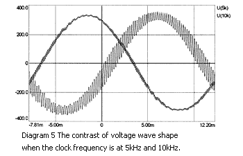
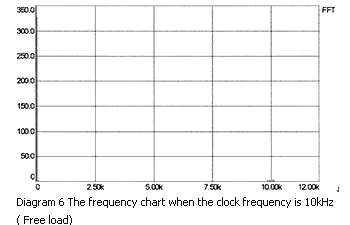
When the compound harmonic distortion is 4.5%, in order to check the value, we can measure it through Norma G?rtz. And then compare with the two figures. If the figure is 4.6%, it shows that the value can bear any questioned. The value is acquired at the worst situation. When rated load is half, the value can reduce to 4.1%. From above we can learn that the total harmonic distortion is less than 4.5% at any case, and will not exceed the fixed value-5%. Using the un-additional capacitor filter is enough. When the quality of output voltage required highly, additional capacitor can be used. When append 2 µF capacitances, the total harmonic distortion is 3.6%, when the additional capacitance is 6µF, the total harmonic distortion is 2.8%.
2. Test process and test outcome
2.1 Total harmonic heft
In order to work out total harmonic heft, we have done a Fu Liye analysis to the wave function. Following wave curve is recorded by oscillograph and deposited in the form of ASCII. After treated with Excel, these files can be read by Simplorer process and be managed continually.
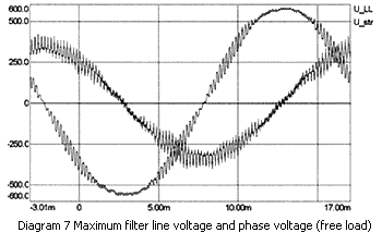
The voltage of middle loop is 630V; the data recorded is when the speed of filter is selected as 10Kbit/s.
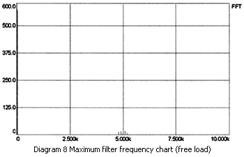
The value of 50kHz fundamental wave heft is UI=568.77V, the harmonic heft is very strong near 5kHz(pulse frequency), U5.097kHz=17.67V.
The calculation of harmonic distortion followed below:
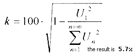
There is some requires on wave shape. The fundamental wave heft should cover 99.5% at least, and the harmonic heft should less 5%. Add some capacitors can cut down harmonic heft (2µF per interval capacitor).
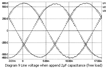
When append 2µF, harmonic distortion reduce to 3.3%( 4µF reduce to 2%). The outcome produced by Norma G?rtz validate the value.
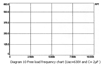
The maximum harmonic value is U4.897kHz=10.7V. There is only a verge difference between free load and load. When the rated load is 12KW, appending 2µF capacitance, the harmonic distortion is 3.4%. Adding 4µF, the harmonic distortion is 1.8%. The test result gain from power analysis instrument validates these data.
Case-filter
Increasing gradually, various electric facilities and equipment always make circuit stay at an anisomerous load situation. The quality of power supply is descending notablely. This situation will also affect the EMC-filter.
Our case-filter can be used in a large scope, and can be divided into two kinds according to circuit construction:
- current compensation reactor
- along induction reactor
Advantage:
- Because the construction is tight and the value of induction is high, the case dimension is small.
- Quick attenuation , begin with 10-14kHz.
- Compare with along induction reactor, the value of induction is higher.
- Compare with along induction mode, for the high inductance value, even reduce the value of capacitance joined in the form of star shape, the filter signal would still attenuate highly.
- Not to produce saturation phenomenon caused by possible anisomerous current, such as syntonic interference.
- Low heat.
Disadvantage :
- If the load of each phase is anisomerous and the difference of wave shape is too large, the effect of current compensation inductance will explode greatly. Meanwhile, it will also produce small stridulation. Filter will not influenced by this stridulation.
- For the low value of inductance, the capacitance should be added accordingly so as to ensure the high increase of attenuation.
- Thereby, because of the increase of capacitance, the leakage current to PE also will increase.
- Compare with compensation filter, the case size is large.
- Compare with compensation filter, the value of inductance is low.
- Generally speaking, this kind of filter is too expensive.
Explanation:
1)If the proportion of non-linear load (convertor) exceed 10~15%, the difference of interphase wave shape is not just a simple sine wave. The impedance of circuitry impedance and shunt-wound filter in the circuit will form a shunt-wound shake circuit. Influenced by the syntonic frequency, the current cause by anisomerous wave shape will reduce for the increase of resistance. At the same time, the decrease of voltage caused by the anisomerous wave shape will increase. As a result, there will be a compensation current between power supply line and filter capacitor. Influenced by asymmetry, the affect of filter current compensation reactor will explode, and then tend to saturation, producing stridulation.
2) The case-filter with high capacitance will blaze a high leakage current to PE. Sometimes ,the leakage current may produce as high as 50% rating current.
Example:
Rating voltage: 230VAC (compare with PE)
Rating current: 16A.
Circuitry frequency: 50Hz
Star shape joint capacitance: 40µF to PE (this value can cause high attenuation within kHz)
Leakage current account value: 3.8A/ Phase
Take into account of above conditions and economical aspect, it is not suitable to use high capacitance filter right now. Mature and reasonable circuit construction is a precondition to guarantee a good filter to be used for several years.
3) High capacitance still has other disadvantages, for it have to enlarge capacitor sizes to reach rating voltage safely. The linear analysis performed by Neubiberg "Bundeswehr Fachhochschule" in Germany shows that spikes and high voltage in private power can reach as high as 3.5KV, and industrial can reach 10KV. And these phenomenons happen sometimes. If the rating voltage of capacitor is too low, it will be penetrated through as loading the high dU/dt. If this phenomenon happens for many times constantly, the capacitor will be destroyed completely. As a consequence, the performance of filter will decrease earlier obviously. The filter depends on the linearity performance. After several months, the filter will not have enough ability to filter.
Modification:
If the users' 3-phase (L1, L2, L3/N) electrical source appears asymmetry, or he doesn't need this asymmetry, we suppose he use the filter of along inductance reactor. The capacitance is more suitable. Therefore, the leakage current which we expect it will some reference with attenuation will be effected strongly. Most of the case- filter adopts the reasonable circuit construction, so that it can load 500VAC along with PE. We can expand it to 1000VAC according to the requirements and wishes of the customers.
At some exception situation, a replaceable voltage protection should be used by filters.